PicoLite (162)
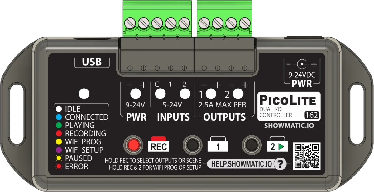
Getting Started
If you aren't sure how to connect to the device please see Getting Started.
Power Input
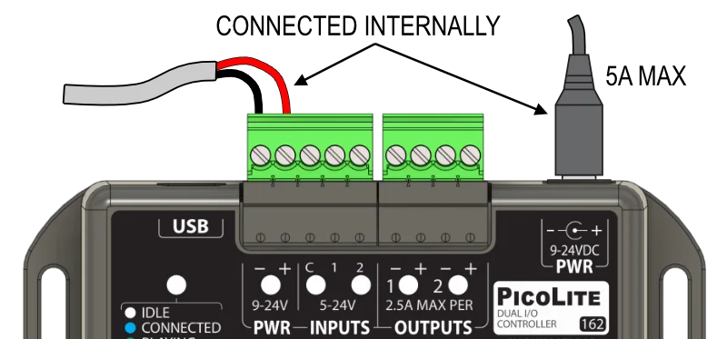
The PicoLite can run on 9 to 24 VDC. The two PWR -/+ terminals and the barrel connector are internally connected together. You can power the unit from either location, or you can power using a barrel connector and borrow that power for a sensor using the screws.
You must make sure your power supply can output enough power for your loads. Please see this page for details on how to correctly choose your power supply.
Input Wiring
The PicoLite has two optically-isolated inputs that can be connected in any polarity making them compatible with a huge variety of sensors.
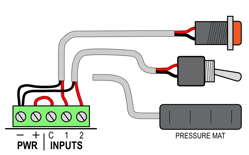
If you only have one just ignore the wires for the second button.
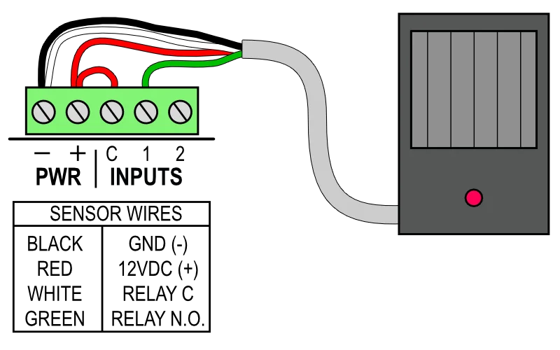
The motion sensor must be 12 VDC, not one made for outdoor floodlights.
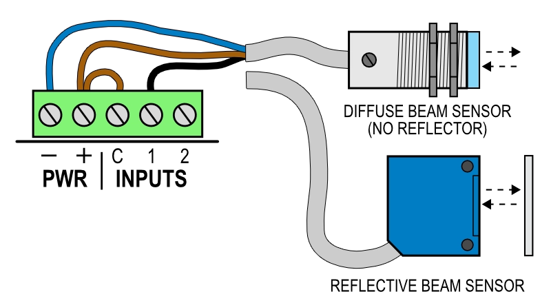
There may also be a mode wire to select normally on/off behavior - see sensor manual.
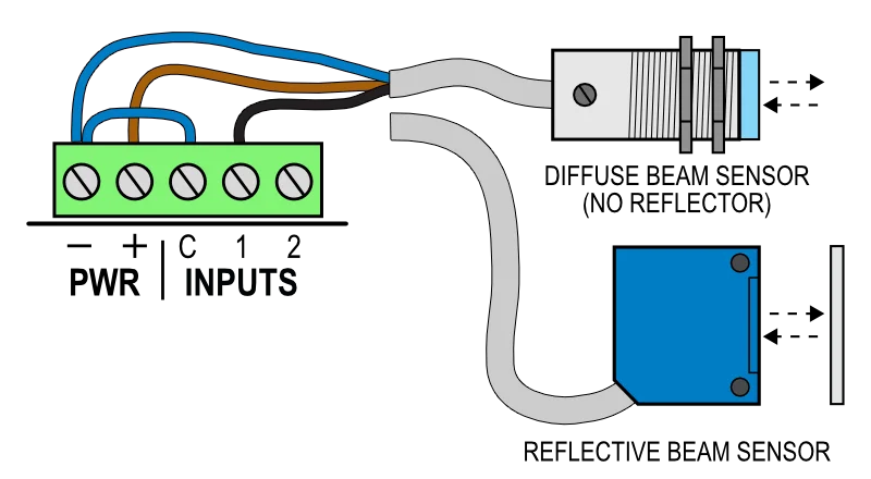
There may also be a mode wire to select normally on/off behavior - see sensor manual.
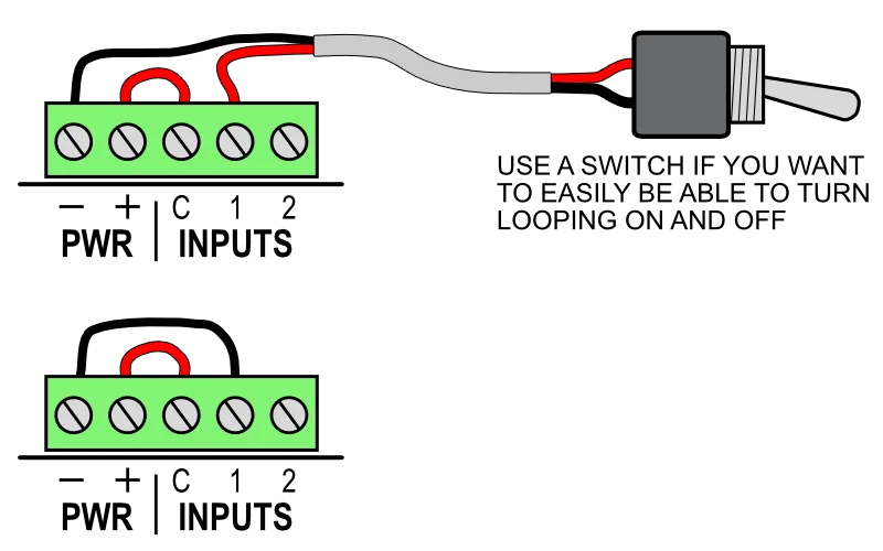
Also see Looping below to do this via software.
For even more input wiring diagrams please see Wiring Diagrams.
Looping
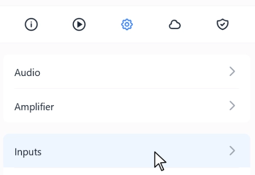
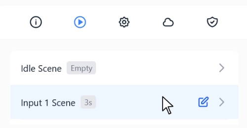
If you want your existing trigger scene to play over and over you can loop it. That can be done with a wire jumper as shown above, or you can do this by changing a configuration option as shown below.
Post Delay
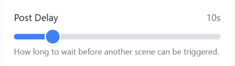
If you'd like a little delay between cycles while it loops you can add a post-delay to the scene.
Output Wiring
The PicoLite has two solid-state outputs. These outputs are great for reliably controlling low voltage DC loads like solenoids, relays, maglocks, or LEDs. When turned on, these outputs output whatever voltage is connected to the power input (12 or 24 VDC). Each output can handle 2.5 amps.
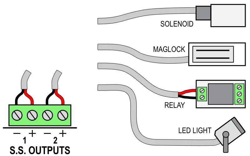
Make sure the device voltage matches your power supply voltage.
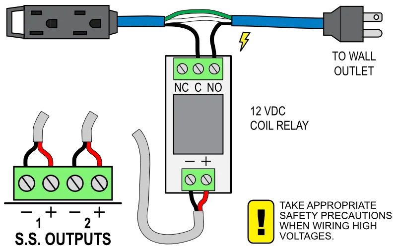
High Voltage devices must be controlled using a relay.
Recording Animation
Animation can be recorded using a phone, computer, or the buttons on the unit. Instructions below are for recording manually using the buttons. For information on recording using the apps or cloud please see the video in Getting Started.
Recording with the Buttons
- Tap REC, the REC LED should turn red.
- Tap or hold the 1-2 buttons to control the outputs.
- Tap REC to stop recording.
- Tap 2 to preview your recording.
Triggering after Recording
The trigger inputs are disabled temporarily while you are recording or previewing animation. This is done to prevent a connected sensor from triggering the scene while you are making changes. The trigger inputs will re-arm after 1 minute, or after you press 2 to preview the scene and let it play to the end. If you try to trigger the scene while the inputs are disabled you'll see the Status LED flash yellow.
Layering Outputs
- To record only one output at a time hold REC until the output LEDs turn on.
- Quickly tap one of the two output buttons to toggle that output on or off for recording.
- Let go of REC when you're done enabling / disabling outputs.
- Tap REC to record, only the output LEDs that were ON will record, the other ones will play back.
Selecting Record Scene
- Hold REC until the output LEDs turn on, keep holding a few more seconds until one or more input LEDs turn on.
- Quickly tap 1 or 2 to select the scene you want to record. The selected scene will be indicated on the input LEDs and will alternate between the button you are pressing and Idle.
- Let go of REC when you're done.
| Scene | Input LEDs |
|---|---|
| Input 1 | 1 |
| Input 2 | 2 |
| Idle | 1 & 2 |
Shortening the Scene
If both outputs are enabled for recording the scene length will always equal the recording length. If you do NOT want to shorten the scene then be sure to have only one of the outputs enabled for recording at any given time.
Show Settings
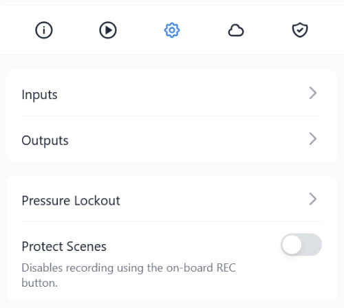
Show Settings for any product can be found in the Configuration tab for that product in the app or on the cloud interface.
Inputs
Label
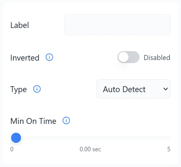
If you are using multiple inputs you can label the inputs here for clarity in the future. Labels like Reset Button, Start Button, etc., could be useful.
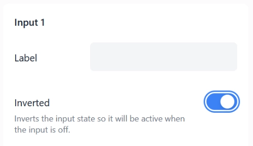
Inverted
If the device connected to the input is outputting a signal that is the opposite of what you need you can invert it. For example, you may be using a limit switch or beam sensor that is keeping the controller's input ON and only turning it OFF when the sensor is triggered. This would cause the controller to loop unless the sensor is kept active.
Usually this can be resolved by using a different sensor output or by connecting a mode wire to + or -. That is the better approach if that's available. If not, enable this option.
Type
Here you can specify the type of sensor connected to the input. With this information the controller can more accurately estimate patron counts and ignore some sensors at start-up as they warm up.
- Auto-Detect: If the input is on at startup the controller will assume a motion sensor is connected. It will wait for up to 1 minute for it to warm up before it allows triggering. This mode will ignore the trigger input for a minimum of 5 seconds at startup as it tries to determine the sensor type.
- On/Off: This mode will allow triggering or looping at startup.
- Motion Sensor: In this mode the input will be ignored at startup. The controller will arm the input once it sees the input state turn off.
Minimum On Time
Set a minimum on time if you need to filter out brief input pulses that are too short to be legitimate input signals. Common use cases include:
- Bouncy Buttons: Buttons or relays with noisy or bouncy contacts can send short trigger pulses when the button is released. These pulses are usually less than a few milliseconds. If you wanted to filter for legitimate button presses you could set this value to a quarter second.
- Interference: Wires act like antennas, picking up electrical energy flying through the air. Devices with coils like Maglocks, solenoids, relays, and motors are prime generators of this kind of noise. In some conditions this noise induces enough of a voltage to trigger an input. This noise is always very short, so adding a very short minimum on time will usually filter it out.
Outputs
Label
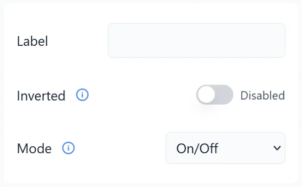
If you have a lot of outputs it can be helpful to label them. These labels will show up in the real-time recording Keypad or in the Timeline Editor so you don't have to guess what output is what before animating. These can also be helpful if you need to troubleshoot remotely and you can't see what device is connected to which output.
Inverted
If you'd like the device to stay on by default and have it turn off when you activate the output during recording you can use this option. This would most often be used for lights you want on most of the time and just need to flicker off once in a while.
If you are trying to invert the position of a pneumatic cylinder it's usually best to do that by swapping the air lines connected to the A/B ports on the solenoid. Inverting it here would keep the solenoid energized all the time, causing it and the output in the controller to heat up and waste power for no reason.
Mode
By default the output will turn on when it's activated, off when it's not. If you need the output to strobe quickly to simulate a strobe light or machine gun effect you can choose one of the Strobe modes. If a strobe mode is selected, the output will strobe off and on at the selected rate whenever the output is activated.
Write Protection
You can enable write-protection by toggling the Protect Scenes toggle at the bottom of the configuration tab (see above). This will disable the record button on the unit and even prevent animation / sound changes in the app.
This is currently the one setting that can also be toggled with the buttons on the unit. To toggle write-protection on the unit itself:
- Power up holding the 2 button.
- After a second or two the status LED will turn solid (see below).
- Let go of button 2.
| LED | Color | Protection State |
|---|---|---|
| Red | Disabled (Recording OK) | |
| Green | Enabled (Recording Blocked) |
Scene Settings
Configuration options for each scene can be found inside the scene menu. Select a scene then look for the Scene Behavior Options.
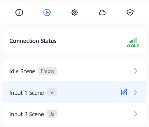
Idle Scene
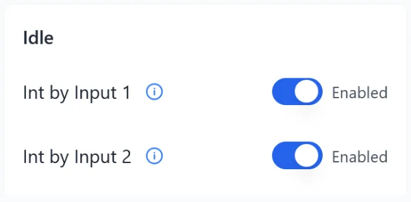
Interruptible By Input X
If you do NOT want an input to be able to trigger a scene when the controller is Idle then disable that input here. A common use case for this would be if you needed to enforce a sequence. Maybe only Input 1 is enabled in Idle, then Input 2 must be triggered from Input 1.
Input Scenes
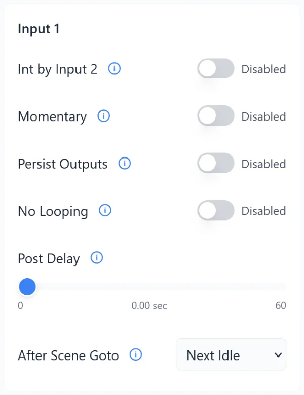
Interruptible By Input X
By default, an input scene is not interruptible by the other input.
Momentary
By default a scene will play to completion once it's been started. If you'd like the scene to only play for as long as the input is active, enable this option. This can give an operator the ability to choose when a scene starts AND stops with a single input.
Persist Outputs
If you need an output to stay on after a scene ends you can enable this option and keep that output on at the end of the scene. Any output that is on at the very last frame of the scene will stay on until another scene is triggered.
This won't work if Idle animation exists because the Idle animation will control the outputs after the scene.
No Looping
By default a scene will loop if the input that triggered it is still on when the scene finishes. If you'd like to prevent looping enable this option.
Post Delay
If you'd like to prevent a prop from activating too often you can enable a Post Delay. The Post Delay starts when the scene finishes and stops when the selected time expires. When active, the REC LED will flash yellow and trigger inputs are ignored.
After Scene Goto
By default, when a triggered scene completes the controller will return to the Idle state and start looping the Idle scene if one exists. If you would prefer the controller to jump to another scene instead, you can select that scene here.
Pressure Lockout
Pressure lockout allows you to disable pneumatic-based props if system pressure is beneath a certain threshold. See the PicoLink page for a video and information on how to set this up.
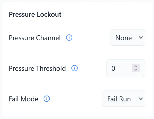
Pressure Channel
Large systems may have multiple pressure sensors. Each pressure sensor must publish its pressure to a dedicated channel. Any number of devices can tune in to a particular pressure sensor by subscribing to its channel.
Pressure Threshold
The prop will ignore its inputs below this pressure.
Fail Mode
If for some reason the controller is no longer receiving pressure data from the sensor what should it do?
- Fail Run: Assume pressure is good and run anyway.
- Fail Safe: Disable the inputs. Only allow triggering if we have confirmation pressure is above our threshold.
WiFi
Connecting to WiFi
Connecting to WiFi happens during the adoption process. Please see Getting Started.
Changing WiFi Networks
Follow the adoption steps to connect the device to a WiFi network, ignoring the final step where you click the Adopt button. The device will not show up for adoption because it's already adopted by you, but it will change WiFi networks.
Disconnecting from WiFi
Hold the two outside buttons on the controller (or only button if it's a PicoLink). The Status LED will turn yellow , then purple , then start flashing purple (Forget WiFi). Let go when its flashing purple. This will tell the device to forget the WiFi credentials so it no longer attempts to connect to WiFi. This process will not unadopt the device so that it can be adopted by another user. If you need to unadopt it that must be done in the app.
Status LED
The status LED's state indicates the device's current state. In some states the LED will blink a few times, pause, then repeat.
| State | Color | Reason |
|---|---|---|
| off | Idle - Not connected to the cloud | |
| 1 blink | Connecting to Access Point | |
| 2 blinks | Connected to WiFi, getting IP | |
| 3 blinks | Received IP, connecting to cloud | |
| steady | Idle - Connected to cloud | |
| steady | Bluetooth provision mode for WiFi setup | |
| steady | WiFi access point mode for direct connection | |
| steady | Playing a triggered scene | |
| steady | Recording | |
| 2 blinks | Trigger post-delay | |
| 3 blinks | Low pressure lockout |
Factory Reset
Factory resetting the unit will erase all settings, animation, and WiFi information. Next time it connects to WiFi it will be removed from the account and need to be re-adopted.
- Unplug the unit.
- Hold the REC button while powering up the unit.
- Status LED should turn RED.
- Let go of REC, the Status LED will begin to flash red.
- The device will flash the Status LED as it erases the internal memory. It will reboot automatically.
Specifications
Part Number
162
Power
Ideal: 12 or 24 VDC
Max Range: 9–28 VDC
Power
0.6 watts
Trigger Inputs
Voltage Range: 5–24 VDC
Current Draw: 2mA @ 5V, 5mA @ 12V, 11mA @ 24V
Solid-State Outputs
Voltage: Same as power input
Current: Max 2.5A steady, 5A for short bursts
Show Storage
Internal: 88KB (50 minutes)
Max Scene Length
Recorded On-device: 2 minutes
Authored In App: 30 minutes
Troubleshooting
Choose the topic that best matches your problem:
If you don't see your issue here, or the troubleshooting steps don't fix it, contact support@showmatic.io and include:
- Product model
- What you expected vs. what happened
- Power and Status LED behavior