PicoLink (170)
Getting Started
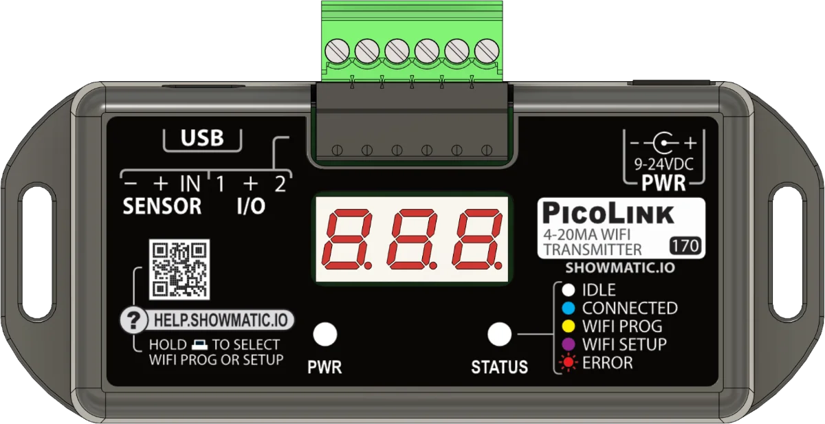
If you aren't sure how to connect to the device please see Getting Started.
Sensor Wiring
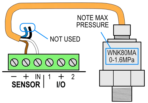
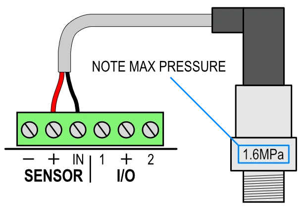
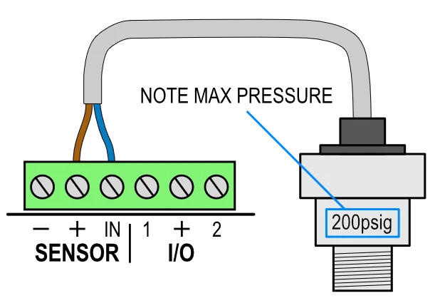
Find the diagram below that matches your sensor. Note the maximum pressure written on your sensor as you will need that during configuration.
PicoLink Setup
Video
Sensor Input
After wiring up the sensor you must tell the PicoLink the rating of the sensor. To do that, open the device's configuration tab...
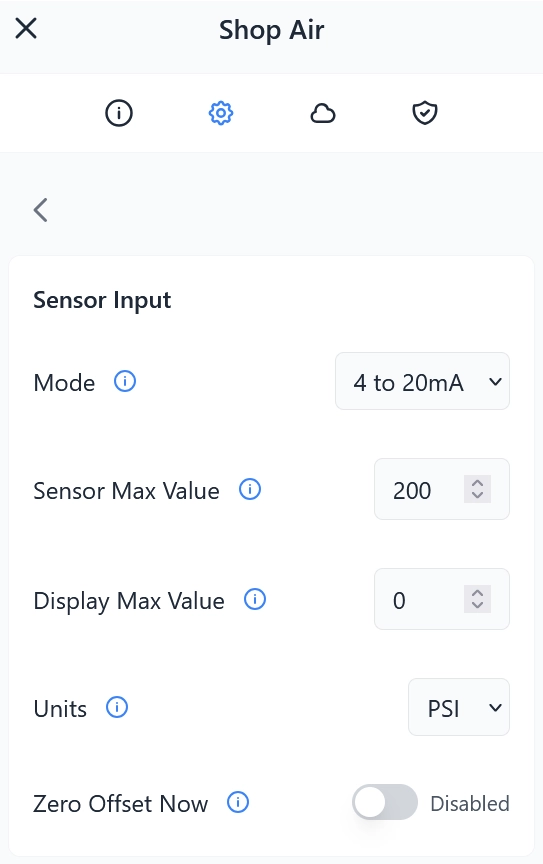
Sensor Max Value
This will be written on the side of the sensor somewhere, either in MPa or psi. If it's MPa, convert to psi by multiplying by 145 (see table below). Type the psi value into Sensor Max Value.
| MPa | psi |
|---|---|
| 1.2 | 174 |
| 1.6 | 232 |
Display Max Value
This is the value you want the user interface elements to use as the maximum for this sensor. The Sensor Max Value of some sensors is likely unreasably high for most setups. If we used that your gauges and bar charts might look half full when your air system is at max pressure.
We recommend entering a value just slightly above your compressor's cut-off pressure. If it stops around 135 or 140, maybe enter 150.
Zero Offset
Some sensors may have a very slight offset, resulting in the PicoLink showing 1 or 2 psi when it's actually zero. To correct this you can zero the sensor. To do that ...
- Disconnect the air from the sensor so that it's "seeing" atmospheric pressure.
- Turn on the "Zero Offset Now" toggle.
- Click Apply.
The PicoLink will use that value as the new zero. The Zero Offset Now toggle will return to the off position.
Pressure Lockout
If you would like one or more of your controllers to pause if pressure is below a certain threshold you can enable Pressure Lockout. To do this you must first create a Channel which the devices use to communicate with each other. You then set one of your PicoLinks and any number of devices to use the channel.
Creating a Channel
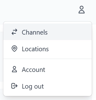
- Click the user menu at the top-right and select Channels from the list.
- Click Create New and enter a channel name.
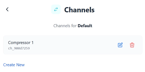
Common names might be ... - Compressor 1 - Compressor 2 - Manifold
Assign PicoLink to Channel
- Go back to the PicoLink config, select Pressure Lockout.
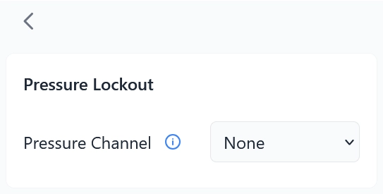
- Select the appropriate channel
Assign Devices to Channel
- Go back to your main Devices list.
- Select one of your animation controllers.
- Open the config tab, select Pressure Lockout, enter you options ...
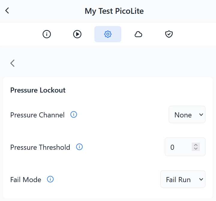
Pressure Channel Select the appropriate channel you want this device to monitor for pressure.
Pressure Threshold Enter the minimum operating pressure for this device. The device will enter a low-pressure standy mode and ignore its inputs if the pressure is below this value. The LED above the REC button will flash yellow if it's in this state.
Fail Mode If this device loses contact with the PicoLink, or the PicoLink is in an error state, what do you want your device to do ...
Fail Run - It will assume pressure is good and continue operation.
Fail Safe - It will stay in standby until it has confirmation pressure is good.