Trigger Input Diagrams
Important
Always disconnect power before making any wiring changes.
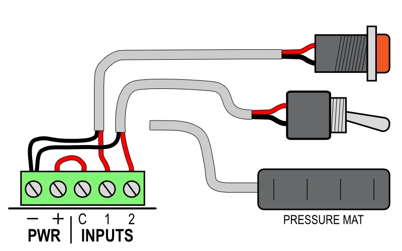
If you only have one just ignore the wires for the second button.
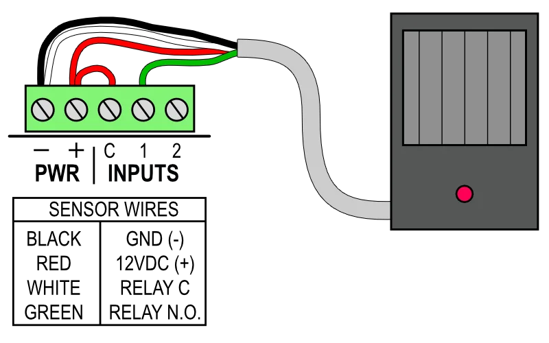
The motion sensor must be 12 VDC, not one made for outdoor floodlights.
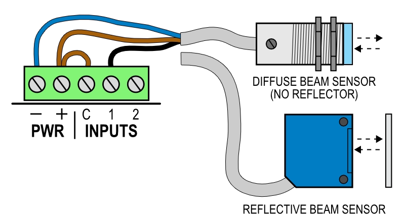
There may also be a mode wire to select normally on/off behavior - see sensor manual.
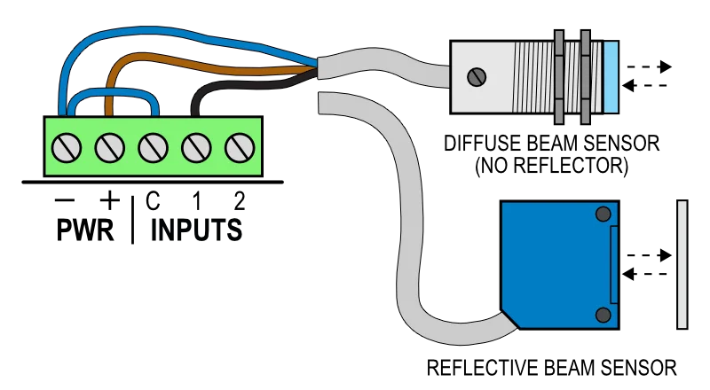
There may also be a mode wire to select normally on/off behavior - see sensor manual.
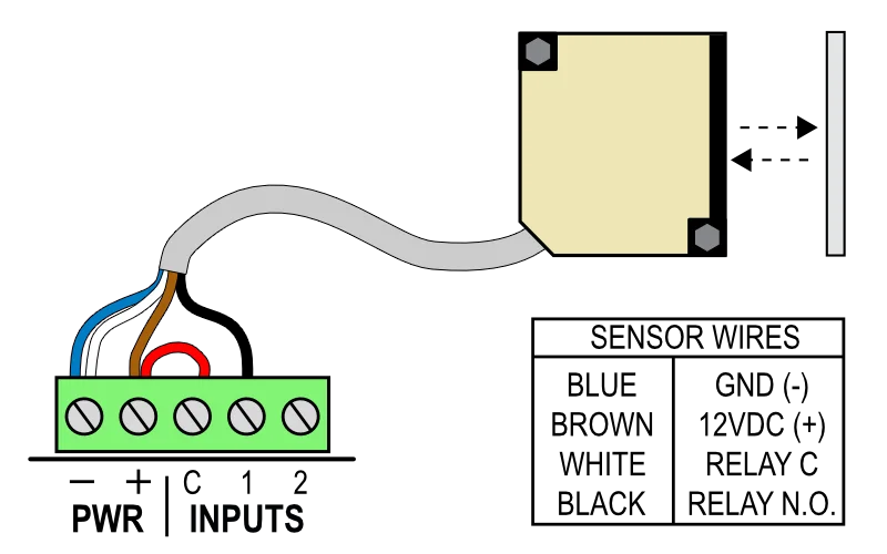
Wire colors may vary by manufacturer. Compare with legend.
Optically Isolating Your Inputs
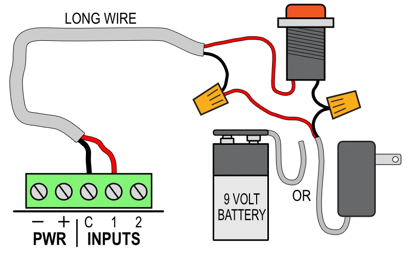
Long trigger wires act like antennas that can bring electrical noise into the controller or even cause the inputs to trigger. If you are powering an input bank by jumpering the Power - or + to C, that interference will get into the controller's power. By removing that jumper and instead powering the inputs from a separate power supply or even a battery, the optical isolation in the inputs prevents the noise from getting into the controller.